The points are on the end of the crankshaft on the other side of the motor.
You are using an out of date browser. It may not display this or other websites correctly.
You should upgrade or use an alternative browser.
You should upgrade or use an alternative browser.
Can anyone explain how the Firefly ignition works?
- Thread starter billirwinnz
- Start date
The photos show a four pole single phase alternator. One thin wire feeds the lights and coil. The only HT lead comes out of the car type coil. This setup is different from traditional energy transfer ignition systems.
If you read above you will see that I have answered my own question and the problem appears to be with the low voltage coming out of the alternator.
If you read above you will see that I have answered my own question and the problem appears to be with the low voltage coming out of the alternator.
Thanks. That's pretty much how the Firefly ignition works except that there is no dedicated ignition coil. The same alternator output serves the lights and ignition.No idea what you have there, but as Vic pointed out, one of the windings is likely dedicated to ignition. Honda used a setup like that. This only shows the ignition side of it.
View attachment 59618
. . . but, but, somewhere there must be an ignition coil ! You want high tension for a spark and this will only come from a dedicated coil ??
Anyway, before trying to overhaul a questionable system with all drawbacks you may consider going for a low cost set as used in most continental mopeds. You can have a simple set with contacts, all on one side and unit. Or if you like CDI plus sensor get one of the million sets for Asian bikes like half of Asia do all commuting.
Vic
Zuendapp ignition
CDI set
Hi Vic
As mentioned above there's a separate conventional coil rather than an ignition coil in the flywheel stator. A condenser and points too.
Replacing the whole setup with something modern is appealing but I'd like to keep the bike original. It worked in 1952 so I should be able to get it working now. It runs fine with a battery which is a simple fix. My problem is definitely in the stator coils as I can only get 1.1vAC at normal pedal starting speeds. I suspect a breakdown in the shellac in one or more coils.
Thanks for the suggestion.
Bill
Last edited:
So my guess your system is like in #6 with an external ht coil fed from the 4 coils within the mag rotor ? So in worst case you´d have four coils for rewinding - and a good idea anyway seeing the stoneage coils.
The nice thing with the Zündapp/Puch breaker type is there are no extra coils on the bike, all components within the mag including the ht coil. But yes, you´d have to machine the rotor for the Firefly crank taper and do an adapter plate . Then you get decent voltage and power, 15 W minimum, 35 W possibly.
Keep us posted how you go along.
Vic
I'm stuck with the Firefly flywheel as the gear is integral to it. Also both the coils and flywheel are very thin to fit in the narrow gearcase. If I was going to go the modern way it would be easier to make up a new stator using new components fitted to match the flywheel diameter. But I'm guessing that the old flywheel magnets despite being re-magnetised would fall well short of those in a modern flywheel.
The 4 coils are riveted together but I will separate them to re-wind them. I'll need some sort of adaptor to hold them in the lathe.
Bill
The 4 coils are riveted together but I will separate them to re-wind them. I'll need some sort of adaptor to hold them in the lathe.
Bill
It mentions the external coil here….
Additional info for the Firefly curious.
 onlinebicyclemuseum.co.uk
Edit… Scroll down to the photos. The HT lead appears to go to the base of the fuel tank and in one photo you can see the coil.
 cyclemaster.wordpress.com
Additional info for the Firefly curious.
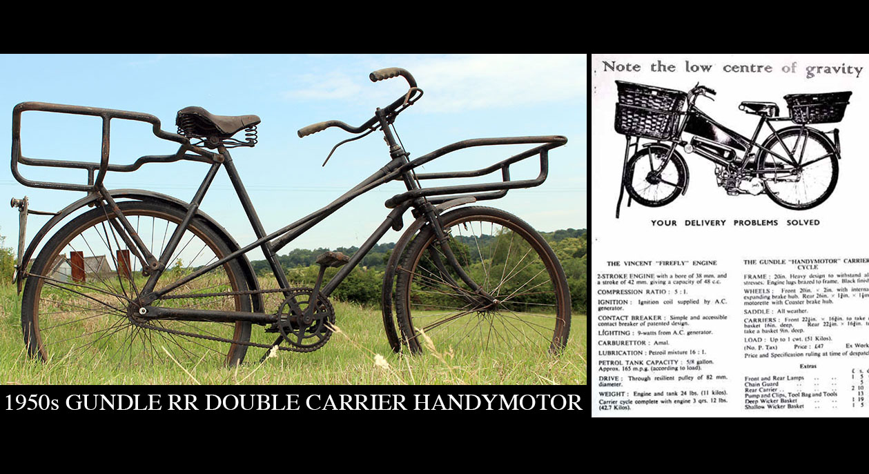
1954 Gundle 'RR' Handymotor (for Vincent Firefly) – The Online Bicycle Museum
1954 Gundle 'RR' Handymotor (for Vincent Firefly)
onlinebicyclemuseum.co.uk
Edit… Scroll down to the photos. The HT lead appears to go to the base of the fuel tank and in one photo you can see the coil.
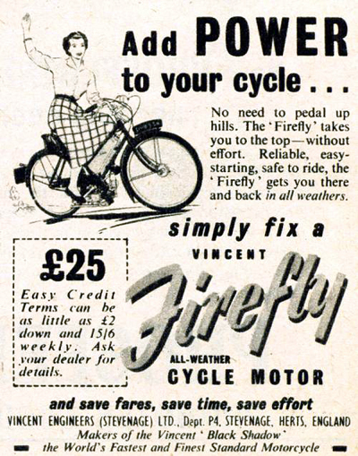
PAGE 14. Vincent Firefly
The Vincent Firefly 1953-1956 The post-war market was not easy for Britain’s motorcycle manufacturers. Throughout Europe, most companies were focusing on small affordable machines to help ord…
cyclemaster.wordpress.com
Last edited:
I’ve used Cerrobend to hold odd shaped parts in the mill or lathe. A small tin or whatever…cut to size filled with molten Cerrobend. Stick the part in and let things solidify.The 4 coils are riveted together but I will separate them to re-wind them. I'll need some sort of adaptor to hold them in the lathe.
Bill
Last edited:
Thanks for the tip. I'll have to google Cerrobend. Much easier than what I was contemplating.