Can anyone explain how the Firefly ignition works?

billirwinnz

Well Known and Active Forum User
VOC Member
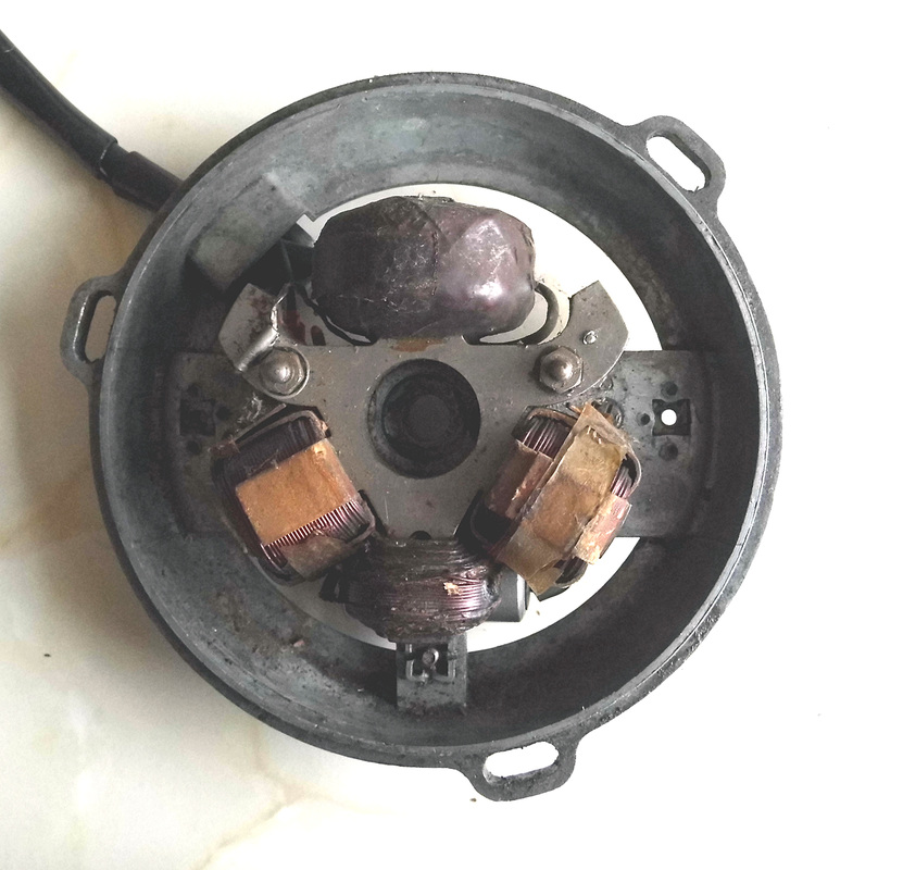
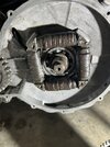
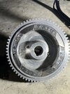
I understand how normal ET ignition works ie "The ET system keeps the primary side grounded until the points open, and then the voltage flows through the primary coil, exciting the secondary coil to produce a spark". Most ET systems have a dedicated primary ignition coil but the Firefly doesn't. If the output is grounded at the points how do the lights work? Does the Firefly work like a conventional battery coil relying on the timing of the alternator pulses and the spark occurring when the primary field collapses?

I've been running my Firefly with a Lucas 6v coil and battery as the original coil has died but I’d like to make it original and also take it on long rides. Does anyone know the original specifications so that I can wind a new coil?

Cheers Bill
 

vibrac

Well Known and Active Forum User
VOC Member
You obviously did not get a reply from you earlier question about the electrical properties of the coil.
Perhaps the manufacturer of the engine (I cant recall who) may be a better source of material documentation
I know the coils on my 98 cc James Comet (!) are very small...
 

billirwinnz

Well Known and Active Forum User
VOC Member
Thanks for your reply. Vincent were the manufacturers of the engine but it was designed by a Polish engineer employed by Miller of lighting fame.

I’ve decided that it must be a conventional coil setup timed so that the points open just after peak voltage on the alternator. I think the magnets are too weak on my bike so I’m trying replacement modern neodymium magnets which I’ve glued in place. Plus I’ve sourced a small low resistance coil from a Husqvarna chainsaw. I’ll know if it’s successful tomorrow.

Bill
 

bmetcalf

Well Known and Active Forum User
VOC Member
I had a 1965 Ducati 250 Scrambler that had some sort of AC ignition. I wonder if it was the same principle?
 

oexing

Well Known and Active Forum User
VOC Member
Bill, can you post pictures of the electrickery ? Ignition can be sort of magneto type and lighting an extra circuit, not connected to ignition !

Vic
 

Cyborg

Well Known and Active Forum User
VOC Member
No idea what you have there, but as Vic pointed out, one of the windings is likely dedicated to ignition. Honda used a setup like that. This only shows the ignition side of it.


E97DB5D1-A6F4-46F4-9C55-B29CF9CCEF69.jpeg
 

Chris Launders

Well Known and Active Forum User
VOC Member
A lot of the vintage two strokes had one or two lighting windings and a separate ignition winding with just a points wire and a HT lead out of it, This is a Bantam one, the big winding is the ignition one, again one points wire and a HT connection.

7850226_orig.jpg


Some types have a laminated core to them that follows the arc of the rotor.
Do you have a picture of your bits ?
 

billirwinnz

Well Known and Active Forum User
VOC Member
Hi

I'm familiar with the energy transfer ignition systems on small Hondas and the Ducati CDI system. The Firefly system is different from both. There is no dedicated primary ignition coil. Just an alternator and a coil with points and condensor like a car. After lots of reading and testing I believe that I know how the system is supposed to work. It's like a cross between a magneto and a conventional coil ignition system.

Instead of the alternator powering a battery which fires the coil via points and condensor, the alternator output goes direct to the coil. The alternator is a 9watt (yes only 9!) unit that outputs 6v AC to drive the bicycle lights and ignition. The alternator drive gear is timed so that the peak of the AC voltage wave occurs just before the points open. For 6v RMS this will be about 8-9 volts which is about the same as the primary voltage in a magneto. From that I deduce that the secondary coil should have about the same characteristics as a secondary coil in a magneto.

I was seeing only 1.1AC volts when I spun the alternator with my drill. Fitting new permanent magnets yielded only 0.9v so today I had the original magnets re-magnetised and re-fitted them. Still only 1.1v so I assume that there must be something wrong with the coils in the stator. That's a job for tomorrow.

Thanks for your interest and suggestions.

I'll let you know how I get on.

Cheers Bill
 
Last edited:

billirwinnz

Well Known and Active Forum User
VOC Member
Here are photos of the alternator stator and flywheel.
 

Attachments

  • IMG_8515.JPG
    IMG_8515.JPG
    307.2 KB · Views: 21
  • IMG_8516.JPG
    IMG_8516.JPG
    400.6 KB · Views: 20

Chris Launders

Well Known and Active Forum User
VOC Member
Yes, that's the sort of thing, but I can't see anything that would operate a set of points, which there should be, surely there's someone on this forum who has a Firefly and can point you in the right direction. The lighting wires would normally be thicker than the HT wire, low voltage/high current as opposed to high voltage/low current.
Current determining your wire size.
One end of everything is probably earthed so there would be a lighting wire, a points/capacitor wire and a HT wire.
 
Top