ET: Engine (Twin) Cases Damaged Due To Race and Bearing Modification? Not Sure...

timetraveller

Well Known and Active Forum User
VOC Member
Ok Chaps. I have now knocked up a CAD drawing of what I was describing a while ago. Several comments first. I am an astronomer, not an engineer, so those of you who are engineers are welcome to make any serious suggestions and I will try and incorporate them into a more complete file. There are several taper roller bearings with a one inch internal diameter so if one wishes to stay with the original diameter main shaft then that is not a restrictions. I have not detailed the taper rollers yet and have just drawn in solid blocks. On these drawings I have used dimensions from one listed bearing and that gives us a wall thickness to the flanged tube of over one quarter of an inch so there is plenty of scope for a larger OD bearing. Additionally taper roller bearings are available with different internal angles which will give more or less strength for the forces expected to be found in our engines. Someone with an engineering background should advise which specification of bearing would be likely to give the longest service. Most of these bearings are specified to work up to about 15,000 rpm so that is not going to be a limit for our engines. For those who wish to go racing then there is plenty of scope to increase the internal diameter of the taper rollers up to, say 30 mm, from one inch and still be well within the space available for this mod. Because I have not chosen a specific taper roller bearing I have not specified all the dimensions of the spacers. I hope the drawings are clear. There is one spacer which is an integral part of the flanges tube and that acts as a stop on the outer races of the back to back taper roller bearings. In addition there is a smaller spacer which fits between the two inners of the taper rollers and it is the combination of these two spacers which controls the preload on the bearings. I have not yet drawn in any detail of the proposed oil seal to go on the outer end of the flanged tube. I need to get a final spec of the bearings before going too far with that detail.
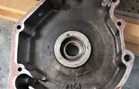
To understand the two drawings imagine that one is looking from the rear engine, forwards. The flange with three counter sunk holes is behind the engine sprocket. The three counter sunk holes would take 1/4" diameter counter sunk screw as drawn. These screws would fasten into the boss in the primary chain case which takes the main bearings. In the engine I have measured this has an outer diameter of about 3.16" with a wall thickness of 0.33"
1676304593259.png


1676304796210.png
 

50BlkShadow

Active Forum User
VOC Member
What is the problem ?,
The bearings have not come out ?,
If you fitted new bearings , They could be ground to fit those small plates.

Do you need to change the bearings ?, Are they worn ?.
The only thing I see wrong is the inner bearings should have staid on the main shafts.

If you needed to fit new bearings, I would fit Lipped outer bearing,
A mod' told in MPH many years ago by Andrew Walker,
Him and his Father were very clever , I think,
Which can't come out, I helped a friend fit these many years ago,
And I have a set ready for my next build.
Just my thoughts.
Bill, the bearings are stuck in the race on both the drive and timing sides and will have to be convinced to make an exit from the races. The bearings also "catch," if you will, with a possible flat spot or something not allowing the bearings to rotate freely. I am installing a new crank assembly from want to make sure that while I am there, I change all of the bearings, but I came across the cut races with the tapped screws in the cases that are tapped all the way through.

I'm sorry for some of my seeming ignorance in this matter, as it is my first time working on a Vincent and the first time I have ever split cases on an engine. I am looking for guidance for this rookie lol
 

50BlkShadow

Active Forum User
VOC Member
I would definitely give Glenn Bewley a ring, he does a great job on this. My norvin main bearing housings were a mess but after he did his thing, absolutely no issue. This is a precision job, I would not just trust anybody to do it.
Great! I have his number and will give him a ring.
 

Bill Thomas

Well Known and Active Forum User
VOC Member
Bill, the bearings are stuck in the race on both the drive and timing sides and will have to be convinced to make an exit from the races. The bearings also "catch," if you will, with a possible flat spot or something not allowing the bearings to rotate freely. I am installing a new crank assembly from want to make sure that while I am there, I change all of the bearings, but I came across the cut races with the tapped screws in the cases that are tapped all the way through.

I'm sorry for some of my seeming ignorance in this matter, as it is my first time working on a Vincent and the first time I have ever split cases on an engine. I am looking for guidance for this rookie lol
Sorry if I came over as Sharp, I am not good with words.

I know you are new to Vincents, Just trying to find you a cheaper way for a fix,
You have certainly gone in the DEEP End !.

I am looking at it as a poor man,
Some on here have big machine shops, And renew and remake at the drop of a hat,
Trying to make Vincents better than new.

I have had and worked on Vincents since 1965,
I know what you mean about the bearings ," Now you say they are stuck ",
The inner main bearing should have stayed on the main shafts,
The outer main bearings are fitted when the engine cases are very hot,
So you also have to heat the cases to get them out,
Till then you don't know what is the problem.

I bought a Ex racing Comet engine a short while ago, With the same problem,
I have not got around to fixing mine yet,
On mine the bigend was the same, And when I took the flywheels apart ,
Found the bearings are NEW !, Just badly put together.

I think you are right to go to someone like Glenn Bewley,
Vincents are one of the hardest bikes to work on.

Hope it can be sorted without to much cost .
Good Luck, Bill.
 

oexing

Well Known and Active Forum User
VOC Member
Norman did nice CAD drawings about a sleeve for the main bearings - I am hopeless with that tech. BUT if that means you have to bore the old bearing seats for maybe 65 or 66 mm from standard 63.5 mm I strongly suggest to look for other ways. The Vincent crank is very wide between mains so I would never ever risk cracked engine cases by boring oversize or drilling screws just for keeping races put. Alternatively I´d like to point you to - shock, horror, another heresy - to metric roller bearings, lipped certainly, with 62mm o.d. . Same size available with taper rollers at 62-30-20 or 16 mm basic dimensions. So then you just preess in an alu sleeve with max. 0.05mm (2thou) oversize into old bores with Loctite 648 spread with fingers on all faces and in a quick action. Certainly the sleeve is undersize i.d. for later line boring the bolted up case halves on the mill. Turning a steel sleeve for adapting the 25.4mm mm mainshaft for 30mm metric bearings is simple enough and will be loctited there as well, nothing wrong with this anyway. So then you got many options from going metric and having PA 66 GF caged roller bearings with lips on various places or two part inner races with extra lips. Forget steel or worse brass cages from olde times, modern types got higher load numbers since decades. Norton called them Superblends in the 70ties for the logarythmic roller shapes then, standard with FAG or SKF since.
In my engines I have two roller bearings on drive side with seal between them. The outer bearing is with two part inner race. I skipped the lip ring and made top hat steel adapters acting as roller bearing lip facing the rollers - plus acting as axial face for the sprocket sitting on it with high spring loads from the poor ESA design and its shock loads in operation. Standard is a ball bearing there , inner race radiused of course so this will eat into the sprocket face and all. Better do your own top hat hardened adapter.
Anyway, a very critical job with these engines, so do serious talks with your machine shop before and asking painful questions about all aspects.

Vic
P1070544.JPG


P1070551.JPG


P1070833.JPG


P1070535.JPG


P1070661.JPG


P1070655.JPG
 

timetraveller

Well Known and Active Forum User
VOC Member
Hi Vic thanks for keeping your eye on my ramblings. However, there is no need to open up the main bearing housing unless it is damaged. The outer diameter of the top hat bush can be made to fit whatever hole is there and in good condition. The only part of the crankcase which has to be machined is the outer end of the main bearing housing to take into account the flange on the top hat bush.
 

Bill Thomas

Well Known and Active Forum User
VOC Member
Has anybody else had Standard Main bearings That won't go easy into the outers ?,
It's hard enough when they are right, The rollers try and tip ,
I had to knock mine out of my outers, On the Project engine I bought,
Like our friend from USA.

I can't understand anybody not trying to slip the inners into the outers,
To see if the fit is right ?,
After fitting the outers into the hot cases ?.
I know we some times have to hone Bigends , But I have never heard of it with Mains.

I can only think the Cases are damaged in some way ?.

You can see on mine where someone has gone MAD banging all the way round the outside !.
 

Attachments

  • IMG_20210827_163710 (2).jpg
    IMG_20210827_163710 (2).jpg
    248 KB · Views: 28
Last edited:
Top