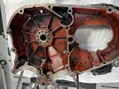
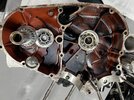
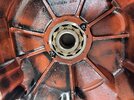
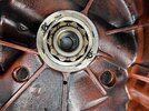
After deciding to do a full rebuild of the engine, I ordered a crank assembly after identifying that there was too much movement in the existing crank assembly. Upon splitting these cases, I stumbled upon the issue below with the bearings. I have been searching the forum to find help, but I think this is now out of my scope. I am questioning the best next steps forward and wether or not these are salvageable. I would appreciate some direction and recommendations.
You are using an out of date browser. It may not display this or other websites correctly.
You should upgrade or use an alternative browser.
You should upgrade or use an alternative browser.
ET: Engine (Twin) Cases Damaged Due To Race and Bearing Modification? Not Sure...
- Thread starter 50BlkShadow
- Start date
Well...
Mmm
Take them out, i presume it doenst go all the way deep.
But for a further 300.K miles doable.
IIf you might think not, i ll have m.
Cheers.
Mmm
Take them out, i presume it doenst go all the way deep.
But for a further 300.K miles doable.
IIf you might think not, i ll have m.
Cheers.
I would not worry too much. This is not an uncommon problem. The mains can be bored and a steel sleeve is installed in each. The sleeve can be a top hat sleeve that can be screwed into the side of the case.

I think you can index the mistakes between the new bearing sleeve holes. If for some reason you cannot, they could be filled with weld prior to machining and the machining should resolve any dimensional problems.
David
I think you can index the mistakes between the new bearing sleeve holes. If for some reason you cannot, they could be filled with weld prior to machining and the machining should resolve any dimensional problems.
David
I agree with both suggestions above. I'd also have made the web a little big bigger before putting in set screws into that tiny web. A lot of staking there as well. Your cases can be line machined, new races/bosses machined up and installed, and your set.
There is a very nice mod which I think is due to Dan Smith It consists of making a top hat bush which is inserted from the outer side of the drive side main bearing. The outer face of the tunnel is machined back to allow for the flange which has three countersunk holes in it to locate it. The outer end of the bush has a left hand thread to take an oil seal. Inside the tube of the bush is an is reduced diameter section. Two back to back taper roller bearings are used with about two to four thou nip. The inner taper roller locates against the face of the drive side flywheel and stops it ever moving sideways. the flywheel assembly cannot move inwards as that motion is controlled by the outer taper roller. As the top hat bush has to be made and its outer diameter can be adjusted to compensate or any work that has to be done to rescue the hole in the crank case it has always seemed to me to be a very nice mod.
Are any drawings or details to do this mod?There is a very nice mod which I think is due to Dan Smith It consists of making a top hat bush which is inserted from the outer side of the drive side main bearing. The outer face of the tunnel is machined back to allow for the flange which has three countersunk holes in it to locate it. The outer end of the bush has a left hand thread to take an oil seal. Inside the tube of the bush is an is reduced diameter section. Two back to back taper roller bearings are used with about two to four thou nip. The inner taper roller locates against the face of the drive side flywheel and stops it ever moving sideways. the flywheel assembly cannot move inwards as that motion is controlled by the outer taper roller. As the top hat bush has to be made and its outer diameter can be adjusted to compensate or any work that has to be done to rescue the hole in the crank case it has always seemed to me to be a very nice mod.
I've only ever seen it as a drawing on a 'cigarette package'. I could draw it up in ACAD but I'm a bit over loaded at the moment. I'll see what I can do.
Sounds vaguely familiar….. Perhaps the birthplace of that mod or early variant?There is a very nice mod which I think is due to Dan Smith It consists of making a top hat bush which is inserted from the outer side of the drive side main bearing. The outer face of the tunnel is machined back to allow for the flange which has three countersunk holes in it to locate it. The outer end of the bush has a left hand thread to take an oil seal. Inside the tube of the bush is an is reduced diameter section. Two back to back taper roller bearings are used with about two to four thou nip. The inner taper roller locates against the face of the drive side flywheel and stops it ever moving sideways. the flywheel assembly cannot move inwards as that motion is controlled by the outer taper roller. As the top hat bush has to be made and its outer diameter can be adjusted to compensate or any work that has to be done to rescue the hole in the crank case it has always seemed to me to be a very nice mod.
It is similar to the one he and his brother did that is residing downstairs in the headstock of my lathe. Done long long ago when they replaced the belt drive with a motor driven through a 4 spd VW gearbox. A lot of hours since it was done. I put an indicator on the chuck… used a 4’ crowbar (with me hanging from it) between the chuck and the carriage …..got zero play. The proof of concept appears to be in the pudding.
In this part of the world we build up the bearing OD (up to .025") with hard chrome, and line bore the cases and put em back together like this The top edge of the bearing race has the c/sunk ground out with a dremel and then the c/sunk screw loctited in.
Dan has done a couple by making a big top hat bushing and screwed it in from the outside, he did some for both timken tapers as in my Rapide (Woolly Mammoth) and back to standard bearings.

Dan has done a couple by making a big top hat bushing and screwed it in from the outside, he did some for both timken tapers as in my Rapide (Woolly Mammoth) and back to standard bearings.