Crank build for racing engine

Pushrod Twin

Well Known and Active Forum User
VOC Member
This is a timely thread for me, I have been tasked by a Section Member to carry out some machining work on a Comet engine to take a 92mm Terry Prince top end.
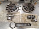
He has also handed me a pair of standard flywheels, conrod and two big end assemblies. The BE's are both 40x48, one with 1.003" shafts, one with 1.125" shafts, both with 7/8" threads. The 1.0" shaft BE falls into the flywheels so the 1 1/8" is the only choice.
The conrod will need the big end honing round, fortuitously, one of the big end bearing rings is over size, but the small end bore has a ridge indicating that it has had a loose bush.

Even if the flywheels and conrod were 100% within standard Vincent tolerances, are they capable of withstanding the extra power generated by a TP top end with MK II cam when being used for spirited road riding?

I would value the opinions of the learned here, please.
 

Attachments

  • 20240401_205930 - Copy.jpg
    20240401_205930 - Copy.jpg
    428.9 KB · Views: 18

DucATIRadeon

Well Known and Active Forum User
Non-VOC Member
the 1.125" is very much likely to be M&S.
check if the sleeve will be a nice (tight) fit in the conrod, I don't think it will matter much as the sleeve has to be honed/ground to size afterwards anyway.

in my conrods the small end bushes were tight, the new bushes from British Only Austria were a lot oversize. so you've got material to play with. I machined them to 0.03~0.04mm interference fit.

tbh: if a twin generates substantial more power (hp and torque) than a single, using essentially the same dimensions mainshafts and bigend and bearings and BE, I wouldn't worry about the capability.
 

oexing

Well Known and Active Forum User
VOC Member
The needle bearing at left side is allright, but the one at right side is NOT suitable for big ends. Think centrifugal forces on the cage when the bearing is positioned at half stroke on a crank. So it gets flung out onto its o.d. floating in the big end bush on oil film. For that it needs substantial faces for floating and the right sort is not designed for this condition. So only take the left type, it was the biggest type 40-48-20mm INA ever made for big ends and many years out of production and no stock so I wonder where it is from. Possibly some dealer had INA make a number of them on order or found a supplier in China who was supplier for INA at that time. I got a number from there as well, so can still supply a bunch of these , the size 35-42-20 too, at € 10.- each. The smaller type was used in the NL ABSAF Goldstar engines when I looked a while ago.
The most important factor for high mileage is clean oil, not the dimension of the bearing. Even when the bearing looks quite strong, any grit entering the track will produce micro defects in the suface and this will go on and destroy the tracks in time, see the Ducati 860 crank pin and conrod with about 30 000km only from new. Well, was a trip to New Delhi and back plus a trip to IOM and not quite back.
When looking at the Maugham cranks I am a bit underwhelmed seeing they still do pressed in mainshafts and bolted up crank pins. Not acceptable for me 30 years ago when I started a lengthy reconstruction of my B Raps, only one piece crank webs plus 30 mm mainshafts would do. My lady Helga spent many hours on that long gone big old lathe roughing out the blocks of ht steel rounds. Yes, finishing them was awkward, unlike a dead simple job with Maughams cranks. But roughing out for integral mainshafts is just some time on a CNC lathe , no troubles with all other details with pressed in mainshafts. Same goes for crank pin nuts - no thanks, pressed in 40 mm pins will only do for me. Even when having my jig for pressing up the lot I got 0,06mm runout that I was unable to true up by hitting the lot with big steel hammer and alu plate on the crank - it would not shift. Well, obviously I am too weak at my age now for hitting it hard enough, the press did it finally. But in fact the heat treated high tensile crank webs plus 40 mm pressed in pin will never ever twist the tiniest amount.
A while ago when in another long telephone conversation with Brufnut we agreed a conical press fit for mainshaft or crankpin with 1 degree taper or half that would be desirable. So you could put shafts in by half the depth , no cocked fault from this then. Next stage you put that under the hydraulic press for final position and good press fit as calculated. Certainly you´d have to machine tapers on mainshafts plus flywheels but no big drama I think.

Vic

YT t.s. runout check clip, metric indicator !! :
crank check

drive side check:
d.s. runout check


P1050474.JPG


P1050608.JPG


P1050616.JPG
P1050484.JPG
 
Top